
Skip to content
HD Engineering & Design
Menu

Project Experience

We possess a wide range of engineering, design, geology, and project management resources.

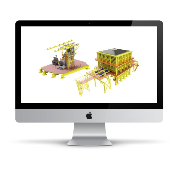
3D model of the 7000 ton coarse ore bin

Coarse Ore Bin

November 2020 marks the construction and commissioning completion of HD’s largest structure to date; a 7000 ton coarse ore bin.

Design

HD took the coarse ore bin from concept, through detailed design. The bin was designed using finite element analysis to Eurocode and S16 standards, using Eurocode bulk material loading and discharge profiles. HD also evaluated the effects of blasting on the bin shell and structure.

The bin and its associated platforms and structures were designed between a 6,000 tph mainline belt conveyor and dual 2,500 tph plow feeders feeding a 2,500 tph reclaim conveyor.

Construction

HD participated in constructability review meetings and shop drawing reviews; working closely with the fabricator and installer to plan the sequencing and weldment sizes to efficiently lower and assemble the bin underground. HD also completed the engineering for the fabricator’s lift plans and structural connections.

HD provided continuous construction support to our client and the installation contractor to develop modifications to the installation plan and construction sequencing to ensure the schedule wasn’t delayed.
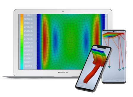
FEA stress model of a miner canopy

Miner Canopy FOPS Engineering

Scope of project involved evaluating the Falling Object Protective Structures (FOPS) on underground mining equipment to determine the maximum energy absorption at the yield strength or buckling capacity for each canopy.

Finite Element Analysis (FEA) software was used to simulate the performance of the canopies under a series of load cases, including distributed loads of various sizes and locations. The maximum load for each case was determined by the first point of failure.

The results of this analysis will be used to develop design criteria to define minimum requirements for future FOPS structures.

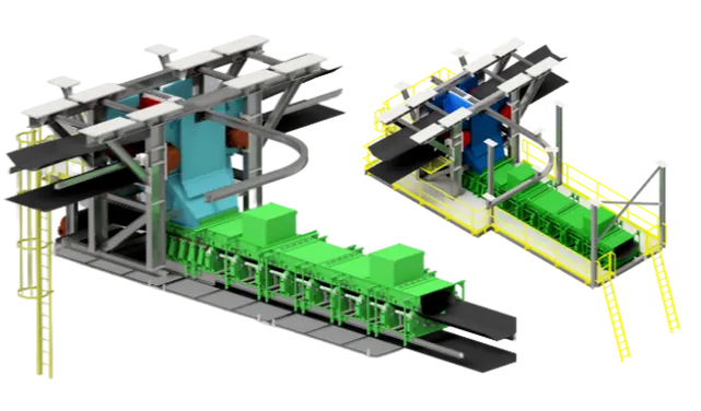
Underground transfer chute model with monorail

UG Chute Design

Our client required the design of a new transfer chute to allow two 54” conveyors to feed a 60” conveyor at 90 degrees. One of the 54” conveyors and the 60” conveyor were existing so the belt centerlines had to be maintained. The scope included DEM modelling to minimize overall height while minimizing dust, and maintaining belt tracking, by strategically locating deflector plates. The loading zone (impact bed, dust enclosure, and skirting) were largely existing and supplied by a competitor who worked with HD to design a new interface. To improve maintenance, HD incorporated a monorail into the design that would support removal of the deflector plates, the chute wall panels, and the head pulleys. Access platforms are to be provided on either side of the 60” conveyor for skirting maintenance as well as above the tail pulley for monorail trolley access.

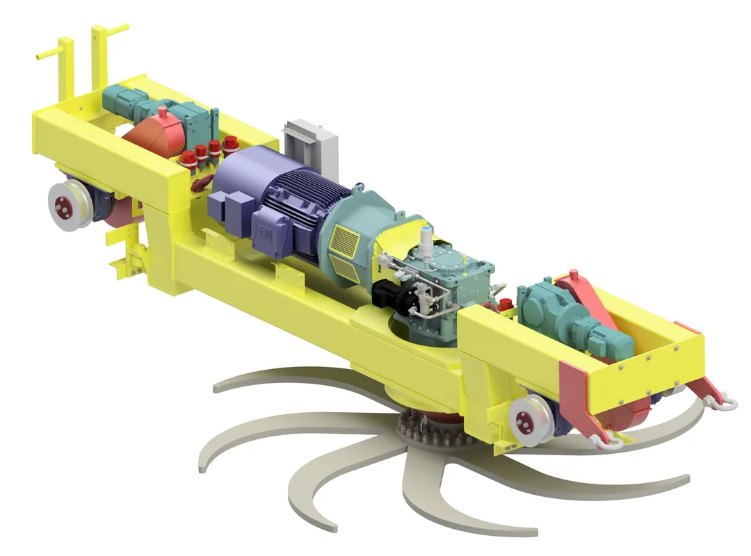
Render of a rotary plow feeder

Rotary Plow Feeder Design

This project involved designing a set of four rotary plow feeders to be used underground at a potash mine. The plow feeders will be installed beneath two raw ore storage bins and feed material onto shuttle conveyors which are part of the conveyance system supplying raw ore to the surface. The project scope included:

  • Electrical engineering for the plow motor, two tram motors, and cooling fan motor
  • Electrical and instrumentation design for zero speed and oil level sensors
  • Festoon cable specification
  • Junction box design
  • Mechanical design and detailing
  • Lifting lug design
  • Lifting plans for shaft lowering and installation
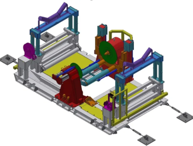
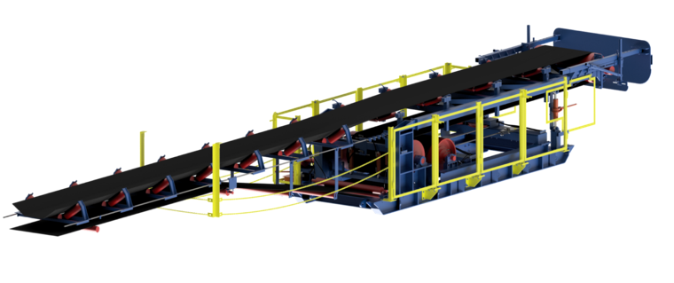
Hydraulic belt winder model

Belt Winder Design

HD completed the design of a belt winder to accommodate a 48″ wide by 63″ diameter roll of belting that weighs 6,700 lb. The belt winder was custom designed to suit a client’s specific requirements for use and functionality. The belt winder was hydraulically driven and includes:

  • Dual belt clamp functions
  • Roll lift (vertically)
  • Roll shift (horizontally)
  • Drive to wind belt
  • Free wheel to unwind belt

The center pivot on non-drive side of the winder was designed to be hydraulically relocated to allow a forklift to place or remove a roll of belting.